
This document is a mechanical specification of a 5 Amp Silicon Bridge Rectifier, which mainly introduces the appearance, terminal configuration, soldering requirements, polarity marking, mounting position, weight, etc. of the product.
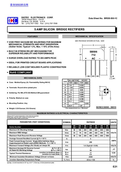
This document is a datasheet for the Diotec Electronics Corp. SB500 through SB510 series of 5 Amp Silicon Bridge Rectifiers. The device features void-free vacuum die soldering and built-in stress relief mechanisms to ensure superior reliability. It is designed for printed circuit board applications with RoHS compliant molded plastic construction.
| Average Forward Rectified Current | 5 Amps |
|---|---|
| Peak Forward Surge Current | 200 AMPS |
| Maximum Forward Voltage (Per Diode) | < 0.95 Volts |
The device can handle a single 60Hz half-sine wave surge of up to 200 amps.
The typical maximum forward voltage is 1.0 volt, though it may be less than 0.95 volts.
The device operates safely between -55 and +150 degrees Celsius.