
This is a 600V half-bridge driver with a floating channel design that can be used for switch mode power supplies and driving N-channel power MOSFETs or IGBTs
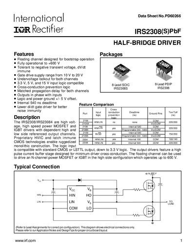
This datasheet describes the IRS2308(S)PbF high‑voltage half‑bridge driver, including its floating channel design for bootstrap operation, gate‑drive supply range, and protection features such as undervoltage lockout and cross‑conduction prevention. It also lists package options (8‑lead SOIC, 8‑lead PDIP) and pin assignments.
Key electrical characteristics are given, such as absolute maximum ratings, recommended operating conditions, dynamic and static performance parameters, and timing diagrams. Mechanical data for tape‑and‑reel packaging and lead‑free part marking information are also included.
| Maximum operating voltage | +600 V |
|---|---|
| Gate‑drive supply range | 10 V to 20 V |
| Package power dissipation (8‑lead SOIC, Ta < +25 °C) | 0.625 W |
| Storage temperature range | -50 °C to 150 °C |
| Lead (soldering) temperature limit (10 s) | 300 °C |
| Turn‑on propagation delay (typical) | 220 ns |
| Turn‑off propagation delay (typical) | 200 ns |
| Deadtime range | 400 ns to 680 ns |
The device is fully operational up to +600 V.
The recommended gate‑drive supply voltage is between 10 V and 20 V.
Typical turn‑on propagation delay is 220 ns and turn‑off propagation delay is 200 ns.