
The IPD60R600CP CoolMOS power transistor features the lowest RON x Qg figure-of-merit, ultra-low gate charge, extreme dv/dt rating, high peak current capability and qualified according to JEDEC1) for target applications.
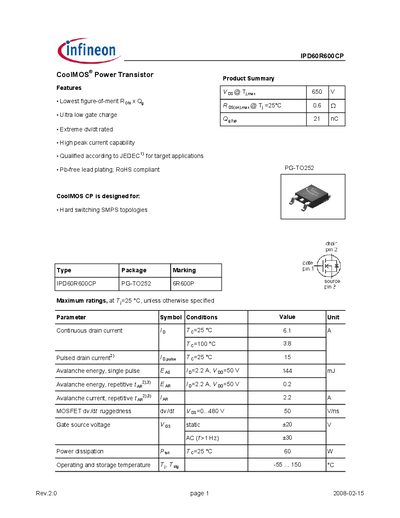
The IPD60R600CP is a CoolMOS® power transistor offered by Infineon Technologies. It is designed for hard‑switching SMPS topologies and features ultra‑low gate charge, high peak current capability, and a low figure‑of‑merit Rds(on)×Qg.
The document provides maximum ratings, thermal and electrical characteristics, dynamic switching parameters, and package dimensions for the PG‑TO252 (6R600P) package. It also includes typical output and transfer characteristics, safe operating area curves, and diode switching data.
| Continuous drain current (Id) | 6.1 A |
|---|---|
| Pulsed drain current (Id,pulse) | 15 A |
| On‑state resistance (Rds(on)) typical | 0.54 mΩ |
| Gate charge total (Qg) | 21 nC |
| Input capacitance (Ciss) typical | 550 pF |
| Output capacitance (Coss) typical | 28 pF |
| Single‑pulse avalanche energy | 144 mJ |
| Power dissipation (Pd) at 25 °C | 60 W |
| Operating temperature range | -55 °C to 150 °C |
The device is rated for a continuous drain current of 6.1 A at 25 °C.
The typical on‑state resistance is 0.54 mΩ when Vgs = 10 V and Id = 3.3 A.
The total gate charge is specified as 21 nC from 0 V to 10 V gate‑source voltage.
The device can dissipate up to 60 W at a case temperature of 25 °C.