
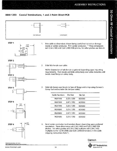
These assembly instructions describe how to install the ITT BBAI-1203 coaxial terminations on 1‑ and 2‑point direct PCB configurations. The guide provides dimensional data, cable preparation steps, and required tooling for a reliable connection.
The procedure is broken into four steps, covering tab‑ferrule placement, crimp body application, cable trimming, and final crimping with a Cannon crimp tool. Notes address optional tab‑ferrule orientation, PCB pitch compatibility, and die‑set specifications for various RG cable types.
| Supported PCB pitches | 2.54 mm (0.100 in) and 7.62 mm (0.300 in) |
|---|---|
| Die size for RG174/U | 3.25 mm (0.128 in) |
| Die size for RG178/U | 2.67 mm (0.105 in) |
| Die set part number | K29263 |
| Supported cable types | RG174/U, RG178/U, RG179/U, RG188/U, RG196/U, RG316/U |
Use Cannon’s Crimp Tool together with the appropriate die set (e.g., K29263).
The terminations fit PCB pitches of 2.54 mm (0.100 in) and 7.62 mm (0.300 in).
Trim the cable to the shown dimensions, being careful not to nick the braids or center conductor, and trim the center conductor as indicated.