
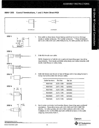
This document provides step‑by‑step assembly instructions for the BBAI-1203 coaxial terminations. It details how to trim the cable, slide the tab‑ferrule, and crimp the body using a Cannon crimp tool and the appropriate die set.
Dimensions for the terminations are given for 2.54 mm (0.100 in) and 7.62 mm (0.300 in) PCB pitches, with additional notes for other pitch multiples. A table lists compatible cable types and the required die size (K29263).
| PCB pitch compatibility | 2.54 mm (0.100 in) and 7.62 mm (0.300 in) |
|---|---|
| Compatible cable – RG174/U | 3.25 mm (0.128 in) |
| Compatible cable – RG178/U | 2.67 mm (0.105 in) |
| Compatible cable – RG179/U | 3.25 mm (0.128 in) |
Use Cannon’s Crimp Tool together with the specified die set (K29263).
The terminations are designed for 2.54 mm (0.100 in) and 7.62 mm (0.300 in) PCB pitches.