
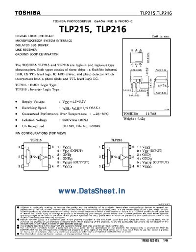
The Toshiba TLP215 and TLP216 are logic‑in/logic‑out type 7a phototransistor couplers that combine a GaAs infrared LED with a TTL‑level output stage. The datasheet provides electrical and switching characteristics, maximum ratings, recommended operating conditions, and example test circuits.
Key sections include pin configuration, electrical characteristics (supply voltage, isolation voltage, input/output levels), switching performance (propagation delay, rise/fall times), and test circuit diagrams for evaluating the devices in a design.
| Supply Voltage (VCC) | 4.5 V – 5.5 V |
|---|---|
| Isolation Voltage | 2500 Vrms (minimum) |
| Propagation Delay (tpHL / tpLH) | 5 ns (max) |
| Output Current | 40 mA (typical) |
The devices provide a minimum isolation voltage of 2500 Vrms.
A supply voltage between 4.5 V and 5.5 V is recommended.
Typical propagation delays are up to 5 ns for both low‑to‑high and high‑to‑low transitions.