
AD9517-2 is a 12-output clock generator with integrated 2.2 GHz VCO. It supports 1 to 32 division and output frequency from 1.6GHz to 800MHz. It supports LVPECL, LVDS and CMOS three output interfaces.
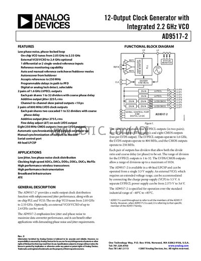
The AD9517-2 provides a multi‑output clock distribution function with sub‑picosecond jitter, an on‑chip PLL and VCO that tunes from 2.05 GHz to 2.33 GHz. It supports differential LVPECL, LVDS and CMOS outputs, each with programmable dividers and fine‑delay adjustment, and can be powered from a single 3.3 V supply.
Typical applications include high‑speed ADC/DAC clocking, wireless transceivers, instrumentation, broadband infrastructure and automated test equipment, where low phase noise and jitter are critical.
| On‑chip VCO frequency range | 2.05 GHz – 2.33 GHz |
|---|---|
| LVPECL output maximum frequency | 1.6 GHz |
| LVDS output maximum frequency | 800 MHz |
| CMOS output maximum frequency | 250 MHz |
| Supply voltage | 3.3 V (±5 %) |
| Operating temperature range | -40 °C to +85 °C |
The on‑chip VCO can be tuned from 2.05 GHz to 2.33 GHz.
It operates from a single 3.3 V supply, with a tolerance of ±5 % (3.135 V – 3.465 V).
It is specified for operation from –40 °C to +85 °C.