
This document provides instructions for using and installing/removing the Gigabit SFP modules (MGBT1, MGBLH1, MGBSX1). It includes steps for inserting the module, removing the rubber port cap, and connecting the fiber cable.
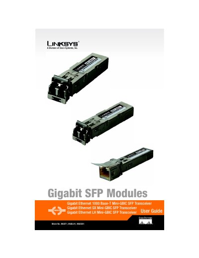
This guide explains how to install and remove the Linksys Gigabit SFP modules (MGBT1, MGBLH1, MGBSX1) in the mini‑GBIC ports of SR2024 or SR224G switches. It includes step‑by‑step instructions with diagrams for both fiber (MGBLH1, MGBSX1) and copper (MGBT1) connections.
The document also provides technical specifications, warranty terms, regulatory compliance information and contact details for Linksys support.
| Dimensions (MGBT1) | 0.33" x 0.53" x 2.60" (8.5 mm x 13.4 mm x 66 mm) |
|---|---|
| Power (MGBT1) | 3.3 V supplied by MiniGBIC port |
| Operating Temperature (All models) | 0 °C to 40 °C (32 °F to 104 °F) |
| Cabling Type (MGBT1) | UTP Cat 5 cable up to 100 m |
| Power (MGBLH1) | 3.3 V, 160‑200 mA (supplied by mini‑GBIC port) |
| Transmitter Power (MGBLH1) | -5 – 0 dBm |
Insert the module with the printed side up and the pull tab facing out, lock it in place, then connect a Cat5 cable to the module’s port.
Linksys offers a one‑year limited warranty that covers repair or replacement of the product for defects in materials and workmanship.
Yes, each Gigabit SFP module can be inserted or removed while the switch is powered on.
The modules operate from 0 °C to 40 °C (32 °F to 104 °F).