
Introduces the default values, communication speed, controller station number, control zone/status zone, controller wiring instructions, etc. of the Mitsubishi Q Series Computer Link man machine
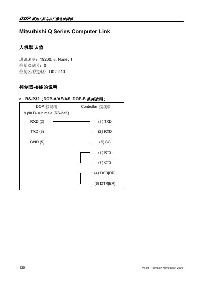
This manual provides the wiring diagrams and connection instructions for Mitsubishi Q Series Human‑Machine Interface (HMI) controllers. It covers default communication settings, RS‑232 and RS‑422 pin assignments, and the address definitions for registers, relays, and timers.
The document also explains how to configure communication parameters using GX Developer software and notes address alignment requirements (multiples of 16 and optional offset of 9000). This manual is written in Chinese.
| Default communication speed | 19200 baud |
|---|---|
| Controller station number | 0 |
The defaults are 19200 baud, 8 data bits, no parity, and 1 stop bit.
Connect RXD on the controller to TXD on the DOP, TXD to RXD, GND to GND, and use the SG, RTS, CTS, and DSR pins as shown in the diagram.
All component addresses must be multiples of 16, or multiples of 16 plus 9000 for special registers.