
This document provides instructions on the Mitsubishi A Series/J71UC24 Computer Link human-machine interface connection, including default values and wiring methods for communication interfaces.
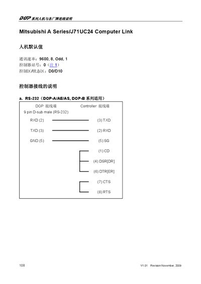
This document provides the wiring and signal definitions for connecting Mitsubishi J71UC24 controllers to external devices via RS‑232, RS‑422, and RS‑485 ports. It lists the pin assignments for each 9‑pin D‑sub connector and the required communication parameters.
The manual also includes the register and contact tables used by the controller, detailing input, output, relay, timer, and counter registers, as well as notes on mode switches and checksum handling for PLC communication. This manual is written in Japanese.
| Baud rate | 9600, 8, Odd, 1 |
|---|---|
| RS‑232 connector | 9 pin D‑sub male |
| RS‑422 connector | 9 pin D‑sub male |
| RS‑485 connector | 9 pin D‑sub male |
| Document revision | V1.01 November 2009 |
The default communication settings are 9600 baud, 8 data bits, odd parity, 1 stop bit.
The manual was revised to version V1.01 in November 2009.
Registers are listed by word number, covering inputs, outputs, link relays, internal relays, timers, counters, and special data registers.