
This document is an instruction sheet for the 5011642700-DNT0 DeviceNet Communication Module (CME-DN01) released on September 25, 2006. The document provides information on the appearance, dimensions, wiring, and settings of the communication module, as well as its feature of not requiring external power and being powered through the RS-485 port connected to VFD-E.
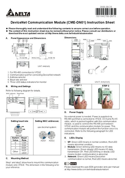
This instruction sheet describes the Delta CME-DN01 DeviceNet communication module, including its panel appearance, dimensions, and the connections required for RS‑485 and DeviceNet networks. It lists the address selector, baud‑rate selector, and three status LEDs that indicate module condition.
The manual explains how to mount the module onto a VFD‑E, shows that no external power is needed because power is supplied via the RS‑485 port, and details the LED indications for normal and abnormal operation. It also provides download links for the latest EDS generator and user manual.
| Dimensions (L×W×H) | 72.2 mm × 35.8 mm × 3.5 mm |
|---|---|
| Baud rate options | 0 = 125 Kbps, 1 = 250 Kbps, 2 = 500 Kbps |
| Power supply | No external power; supplied via RS‑485 port |
| LED indicators | Three LEDs (SP, Module, Network) show normal/abnormal status |
The module does not require an external power source; it receives power through the RS‑485 connection to the VFD‑E.
The SP LED shows green for normal and red for abnormal; the Module LED blinks green when no MO data is transmitted, stays green when data transmission is OK, and red indicates abnormal communication; the Network LED is green for normal DeviceNet communication and red for abnormal.
Use the baud‑rate selector switch: position 0 selects 125 Kbps, position 1 selects 250 Kbps, and position 2 selects 500 Kbps.