
Key facts
- Brand
- Emerson
- Model
- PTF20
- Industry
- Industrial
- Documents
- 2
- Languages
- EN
- Last added
- 2012-07-10
Start here
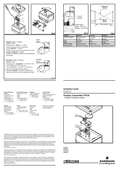
Emerson PTF20 Position Transmitter Installation Guide
This document provides the installation guide for the Emerson PTF20 Position Transmitter option. It details the components included in the kit, such as the position transmitter card, screws, and spacers. The guide explains how to mount the electronic card onto the positioner's main board and secure it with three bolts. It also covers the pre-wiring of the potentiometer and the necessary electrical connections.
Read onlineEmerson PTF20 specifications
| Potentiometer Resistance | 50 kOhm |
|---|---|
| Maximum Voltage | 30 VDC |
| Minimum Voltage | 15 VDC |
| Output Signal | 4 - 20 mA |
| Operating Temperature | -20°C to +80°C |
| Wiring Dimension | 1.5 mm² / 14 AWG |
| Turning Moment | 0.8 Nm / 7 in/lb |
Source: Emerson PTF20 Position Transmitter Installation Guide
All Emerson PTF20 documents by type
Mounting, wiring and first power-up. Read it before the hardware goes in.
Questions answered in these manuals
How do you change the feedback signal from 4-20 mA to 20-4 mA?
You can reverse the feedback by means of two jumpers.
What is the required turning moment for the installation?
The required turning moment is 0.8 Nm or 7 in/lb.
What standards does the F20 positioner comply with for ATEX?
The positioner complies with EN 60079-0: 2006 and EN 60079-11 : 2007.
What must be ensured before the positioner is put into operation?
The machine into or onto which the positioner will be installed must comply with the stipulations of the Machinery Directive.