
This document is the installation guide for PTF20-Posiflex Positioner. It introduces the features and characteristics of PTF20-Posiflex Positioner, installation methods, connection cables and other information.
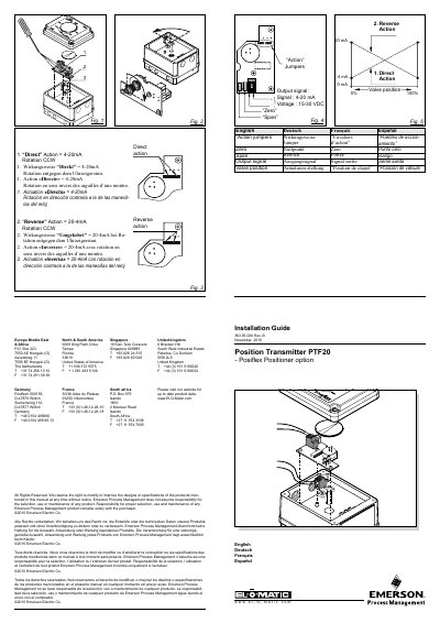
This document provides the installation guide for the Emerson PTF20 Position Transmitter option. It details the components included in the kit, such as the position transmitter card, screws, and spacers. The guide explains how to mount the electronic card onto the positioner's main board and secure it with three bolts. It also covers the pre-wiring of the potentiometer and the necessary electrical connections.
| Potentiometer Resistance | 50 kOhm |
|---|---|
| Maximum Voltage | 30 VDC |
| Minimum Voltage | 15 VDC |
| Output Signal | 4 - 20 mA |
| Operating Temperature | -20°C to +80°C |
| Wiring Dimension | 1.5 mm² / 14 AWG |
| Turning Moment | 0.8 Nm / 7 in/lb |
You can reverse the feedback by means of two jumpers.
The required turning moment is 0.8 Nm or 7 in/lb.
Three screws are required to fix the electronic card to the main board.