
This document is the user manual for Delta DVP series programmable controllers, which provides information on electrical specifications, functional specifications, installation wiring, troubleshooting, and peripheral devices. The product features an open type casing and must be installed in a dust-proof, moisture-proof, and electric shock/impact-free enclosure. The document also includes precautions for input power and AC input power, as well as model specifications and appearance introduction.
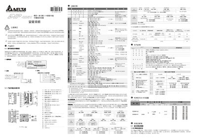
The Delta DVP-28SV11R/T is a 28‑point (16 inputs + 12 outputs) programmable controller with a 16 K‑step program memory and support for a wide range of expansion modules. The manual provides detailed information on the controller’s hardware layout, input/output specifications, and built‑in functions.
The guide explains how to install the controller in a protected enclosure, connect the power supply, wire input and output points, and perform initial testing. Safety precautions, battery maintenance, and troubleshooting of error indicators are also covered to ensure reliable operation. This manual is written in Chinese.
| Power supply voltage | 24 VDC (20.4 VDC ~ 28.8 VDC) |
|---|---|
| Maximum input current | 2.2 A @ 24 VDC |
| Power consumption | 6 W |
| Insulation resistance | ≥ 5 MΩ |
| Weight | 260 g |
The controller requires a 24 VDC supply; the acceptable range is 20.4 VDC to 28.8 VDC.
Insert the plastic fixing piece at the bottom of the PLC, then hang the PLC onto the DIN rail and press down to lock it in place.
Check all wiring before powering on and never connect AC 110 V or AC 220 V directly to the input terminals; the controller must be powered with 24 VDC only.