
This document mainly provides installation, wiring circuit, and commissioning references for the 01PU positioning control module. For further instructions on usage, please refer to the 'DVP-PLC Application Technical Manual' [Special Module Edition]. Do not touch any terminals when powering on. Make sure to close the power supply when wiring. The module is an open-type casing and must be installed in a dustproof, moisture-proof, electric shock/impact-free enclosure wiring box. It must also have protective measures (such as special tools or keys to open) to prevent non-maintenance personnel from operating or accidentally impacting the body, causing danger and damage. The AC input power must not be connected to the input/output signal terminal, otherwise it will cause serious damage. Please confirm the power wiring again before powering on.
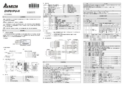
The guide explains how to safely install the DVP01PU-H positioning control module, including required precautions such as turning off power before wiring and avoiding contact with terminals. It describes the module's physical layout, DIN‑rail mounting, terminal assignments, and RS‑485 communication setup.
Technical information covers the module's input specifications, pulse output capabilities, supported motion modes, and register mapping (CR#0‑#53). Environmental limits, error codes, and troubleshooting steps are also included to aid maintenance and commissioning. This manual is written in Chinese.
| Input Current | 140 ± 30 mA |
|---|---|
| Maximum Pulse Output | 200 KPPS |
| Maximum Connected Axes | 8 |
Turn off the power and do not touch any terminals before applying power.
The module can connect up to 8 axes.
It can output pulses up to 200 KPPS.