
The Model 5550 Mechanical Vibration Switch offers basic protection against gross changes in structural seismic acceleration. Its operating mechanism is purely mechanical and consists of a tension spring attached to a pivoting plate on an over-center fulcrum – magnets are not employed. Normally, this plate is in an untripped position. However, in the presence of sufficient seismic acceleration (whether vibratory or impact), the trip plate will pivot beyond this over-center position, snapping to a stable tripped position where it contacts an internal microswitch relay, changing the state
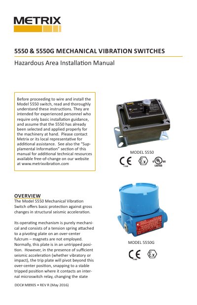
Metrix 5550 and 5550G mechanical vibration switches provide basic protection against gross changes in structural seismic acceleration using a purely mechanical trip mechanism. This hazardous area installation manual covers mounting, conduit, wiring, setpoint adjustment, remote reset and startup lockout, and safety information.
The switch trips when sufficient seismic acceleration moves a pivoting plate past an over-center fulcrum to actuate an internal microswitch relay. After tripping, it must be reset manually or with the optional remote electrical reset; the same circuit can provide up to 30 seconds of startup lockout.
| Conduit thread (NPT) | 3/4 inch NPT |
|---|---|
| Conduit thread (metric) | M20 x 1.5 |
| Cover screw torque | 6-7 ft/lbs |
| Setpoint adjustment range | approximately 2 full turns (16 g peak) |
| Minimum setpoint adjustment | approximately 1 g per 1/8 turn |
| Factory default setpoint (upward vertical) | approximately 2 g |
| Factory default setpoint (horizontal) | approximately 1 g |
| Startup lockout duration | up to 30 seconds |
| Field wiring temperature rating | suitable for minimum ambient temperature |
Turn the set screw on the cover clockwise to increase the setpoint and counterclockwise to decrease it; about 1/8 turn equals about 1 g.
Up to 30 seconds, or as long as voltage is continuously applied, whichever is shorter.
NPT conduit holes use 3/4 inch NPT threads and metric conduit holes use M20 x 1.5 threads.
No, it is not intended for high-speed turbomachinery or for detecting changes in seismic acceleration smaller than 1 G.