
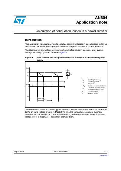
This application note explains how to calculate conduction losses in a power diode by taking into account the forward voltage dependence on temperature and the current waveform. The ideal current and voltage waveforms of an ultrafast diode in a power supply system during a switching cycle are shown in Figure 1.
The document details the factors influencing conduction losses in power rectifiers, specifically focusing on the forward voltage drop's relationship with junction temperature. It introduces a modeling approach using threshold voltage (Vto) and dynamic resistance (Rp) to accurately estimate these losses across different operating conditions.
The guide provides basic equations for calculating average and RMS currents under various waveform shapes, such as square, trapezoidal, sinusoidal, and triangular waves. An application example is included demonstrating the calculation of maximum conduction losses in a 90 W notebook adapter using an ST power Schottky diode.
The calculation takes into account the forward voltage dependence on temperature and the current waveform.
They must be calculated using specific application conditions rather than just standard datasheet values, often requiring calculation at two different junction temperatures.