
The AD9981 is the first display electronics (DEPL) device to incorporate the auto-offset function. The auto-offset function works by calculating the required offset setting to yield a given output code during clamp. When auto- offset is enabled (Register 0x1B:5 = 1), the settings in Registers 0x0B – 0x10 are used by the auto-offset circuitry as desired clamp codes (or target codes) rather than an offset value. The circuit compares the output code after clamp (but still during the “back porch”) to the target code and adjusts the offset up or down to compensate. In auto-offset mode, the target code is an 11-bit twos complement word, with Bit 7 of 0x0B being the sign bit for the red channel (Bit 7 of 0x0D for green; Bit 7 of 0x0F for blue).
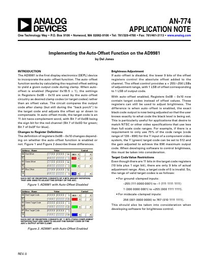
The document describes the auto-offset function of the AD9981, which calculates the required offset setting to yield a given output code during clamp. When enabled, the device uses specific registers as target codes rather than offset values, comparing the output code after clamp to these targets to adjust the offset automatically.
| Offset adjustment range | + 255/-256 LSBs |
|---|---|
| Target code bits | 11-bit twos complement |
| Evaluation time range | 16 to 40 data clock cycles |
To activate the auto-offset mode, set Register 0x1B, Bit 5 to 1.
The range is from -255 to -1 and from 1 to +255.