
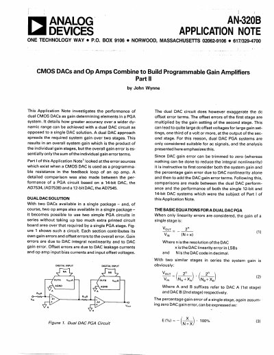
Part II of this application note investigates the performance of dual CMOS DACs used as gain-setting elements in a PGA system. It details how greater accuracy over a wider dynamic range can be achieved with a dual DAC circuit compared to a single DAC solution by spreading the required system gain over two stages.
The document provides theoretical analysis, including basic equations for dual DAC PGA systems and comparisons of error sources such as integral nonlinearity and gain error. It compares the performance of a dual 12-bit DAC (AD7547LN) against single 12-bit and 14-bit DAC solutions, discussing dynamic problems related to stability and compensation in these circuits.
| Resolution | 12 bits |
|---|---|
| Relative Accuracy (Integral Linearity) | +1/2LSB max |
| Gain Error | +1LSBmax to +2LSBmax |
| Output Leakage | 10nA max to 250nA max |
| Input Resistance | 20kΩ max |
A dual DAC approach spreads the required system gain over two stages, resulting in an overall system gain which is the product of the individual gain stages, but the overall gain error is essentially only the sum of the individual gain error terms.
No, they are generally considered suitable only for AC signals because the offset errors of the first stage are multiplied by the gain setting of the second stage, which can lead to large DC offset voltages.
The AD7547LN, a dual 12-bit DAC with full parallel loading housed in a skinny 24-pin package.