
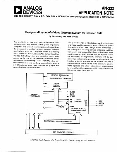
Analog Devices AN-333 Application Note Design and Layout of a Video Graphics System for Reduced EMI


Analog Devices AN-333 Application Note Design and Layout of a Video Graphics System for Reduced EMI - cover page
Brand
Analog Devices
Document type
Application Note
Language
English
Pages
16
File format
PDF
File size
1.5 MB
Published
02 August, 2012
Updated
24 August, 2012
Model
AN-333
MD5 checksum
A01F68BAE0757CBCE079847C160A2C63

About this manual

This document serves as a guide for designers creating video graphics systems, specifically focusing on minimizing Electromagnetic Compatibility (EMC) issues. It addresses the challenges of incorporating low-cost, high-performance Video RAM-DACs into personal computers or plug-in boards while adhering to regulatory limits like FCC Part 15.

The text identifies key noise sources within such systems, including crystal oscillators, fast transition logic circuits, unterminated lines, stray inductance/capacitance, and switching power supplies. It offers specific strategies for mitigating these issues through careful component placement, isolation techniques (such as using ferrite beads), and the selection of appropriate logic families with slower rise/fall times.

What's inside

  • International EMI Regulatory Bodies
  • System Noise Identification
  • PCB Layout & Design
  • Crystal Oscillators and Clock Control
  • Logic Families Transition Times
  • Switching Power Supplies
  • Video RAM-DAC Output Filtering

Specifications

CMOS (74HC) Logic Family Transition Time20-150 ns

Frequently asked questions

How should crystal oscillator circuits be placed to reduce EMI?

They should be placed as far as possible from analog circuitry and video output connectors.

What is the maximum permissible radiation field strength for a Class B computing device between 30 MHz and 88 MHz at a distance of 3 meters?

The maximum permissible radiation field strength is 100 uV/Meter.

What is the recommended maximum distance between buffers when distributing low power data drivers for clock and pixel data lines?

A distance of less than three inches between buffers would be desirable.

Download PDF (1.5 MB)

More Analog Devices Manuals


View all Analog Devices manuals →