
This application note presents practical step-by-step design considerations for an interleaved Boundary-Conduction- Mode (BCM) Power-Factor-Correction (PFC) converter employing Fairchild PFC controllers FAN9611 and FAN9612. It includes designing the inductor and Zero- Current-Detection (ZCD) circuit, selecting the components, and closing the control loop. The design procedure is verified through an experimental 400W prototype converter. The FAN9611/12 interleaved dual BCM PFC controller operates two parallel-connected boost power trains 180º out of phase, extending the maximum practical power level of this control technique from 200-300W to greater than 800W. Unlike the Continuous Conduction Mode (CCM) technique often used at this power level, BCM offers inherent zero-current switching of the boost diodes (no reverse-recovery losses), which permits the use of less expensive diodes without sacrificing efficiency. Furthermore, the input and output filters can be made smaller due to ripple cancellation between the power stages and the effective doubling of the switching frequency. The advanced line feed-forward with peak detection circuit minimizes the output voltage variation during line transients. To guarantee stable operation with less switching loss at light load
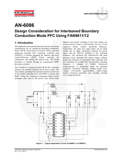
This document presents practical step-by-step design considerations for an interleaved Boundary-Conduction-Mode (BCM) Power-Factor-Correction (PFC) converter employing Fairchild PFC controllers FAN9611 and FAN9612. The note explains how interleaving two parallel-connected boost power stages 180° out of phase extends the maximum practical power level of this control technique to greater than 800W, overcoming the limitations of single-stage BCM converters.
The maximum switching frequency is clamped at 525kHz to guarantee stable operation with less switching loss at light load.
The design specifications require a minimum switching frequency that is higher than 50kHz.
The design example specifies a nominal output voltage of 400V and a current of 1A.