
The MAX100 evaluation kit (EV kit) allows high-speed digitizing of analog signals at 250Msps, using the MAX100 ADC. All circuitry required to support the ADC is supplied. Data output is available in three formats: divide-by-1, divide-by-2, or divide-by-5 mode. Clocking is provided by an external clock source input through an SMA connector. The MAX100 EV kit main board comes complete with a MAX100 high-speed, 8-bit flash ADC with strobed comparators, latched outputs, and an internal track/hold. Analog input to the board is through two SMA coaxial connectors, for use with either differential or single-ended inputs. Signals from the main board include dual-output data paths that allow easy interfacing to external circuitry. These two outputs can be configured either to provide two identical fast outputs (A and B), or an 8-to-16 demultiplexer mode that reduces the output data rates to one-half the sample clock rate. This demux is internal to the MAX100 ADC and is one of the key features of this device. A termination board with 50Ω ECL pull-down resistors is also supplied, and is connected to the main board with a 3x32 pin EURO-card connector. It provides access to the converter output data and provides proper ECL data termination. In addition to the pull-down resistors, this board has two ranks of square pins, each providing eight differential data outputs plus clock outputs. Either AData or BData may be observed with a high-speed logic
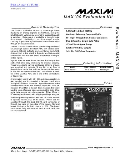
The document provides a general description of the MAX100EVKIT evaluation kit, which supports the MAX100 8-bit flash ADC. It details the board components, including the main board with the ADC and a termination board for ECL data output.
The guide includes quick start instructions for connecting power supplies (+5V and -5.2V), clock sources, and analog inputs. It also explains detailed operational modes controlled by DIP switches, signal phasing, reference voltage adjustments, and specific requirements for PCB layout to ensure proper high-speed performance.
| Effective Bits | 6.8 at 125MHz |
|---|---|
| Sample Rate | 250Msps |
| Resolution | 8-bit flash ADC |
| Input Signal Range | +/-270mV |
| Output Type | 100k ECL Outputs |
| Power Dissipation | 12W |
The kit requires +5V and -5.2V power supplies with a common ground.
Plug the termination board into the 96-pin connector of the MAX100 EV kit board.
Use a fan to provide at least 200 lineal feet per minute airflow to the heatsink.