
The MAX1011 evaluation kit (EV kit) simplifies evaluation of the 90Msps MAX1011 6-bit analog-to-digital converter (ADC). The kit includes the basic components necessary to operate the on-chip oscillator as a voltage-controlled oscillator (VCO). The board can also be easily modified to accommodate an external clocking source. Connectors for power supplies, analog inputs, and digital outputs simplify connections to the device. The PC board features an optimized layout to ensure the best possible dynamic performance. The EV kit includes a MAX1011.
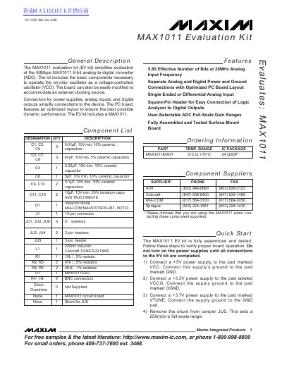
The document provides a general description and quick start instructions for the MAX1011 EV kit. It details how to connect power supplies (VCC, VCCO, VTUNE) and signal sources to verify proper board operation using a logic analyzer.
Detailed sections cover jumper configurations for gain selection and offset correction, analog input requirements, and voltage-controlled oscillator (VCO) operation. The guide also explains how to modify the kit to accept an external clock source instead of the internal VCO.
| Effective Number of Bits (ENOB) | 5.85 bits at 20MHz Analog Input Frequency |
|---|---|
| Analog Power Supply Voltage | +5V |
| Digital Outputs Supply Voltage | +3.3V |
| VTUNE Control Voltage Range | 0V to 8V |
Use jumper JU5 to manually select the desired gain range: Low-gain (500mVp-p), Mid-gain (250mVp-p), or High-gain (125mVp-p).
Remove components like the varactor diode and inductor, replace resistors with 49.9Ω values, add a BNC connector at J2, and connect an external clock signal to the CLOCK OVERDRIVE pad.