
This document discusses the testing and evaluation of voltage regulators under transient loads, as well as practical considerations in testing.
The document addresses the necessity of testing voltage regulators to ensure they maintain stable output voltages under transient loads caused by semiconductor memory, microprocessors, and other digital systems. It explains that while ideal regulation implies an invariant output during transients, practical variations often exceed allowable tolerances.
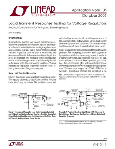
Two primary methods for generating these test loads are detailed: a basic load transient generator using switched resistive loads and a more versatile closed-loop circuit capable of linearly controlling instantaneous current. The text provides circuit diagrams and performance data comparing FET-based and bipolar transistor implementations of the closed-loop tester.
The circuit can cleanly switch a 1A load in 15ns.
The circuit can switch a 1A load in 15ns.
The A1 output only needs to swing 50mV.
The amplifier has an output current capacity exceeding 1A.