
The MC-NOVE is a microcontroller development board based on the ATmega328 microcontroller. It has 14 digital input/output pins (of which 6 can be used as PWM outputs), 6 analog inputs, a 16 MHz crystal oscillator, a USB connection, a power jack, an ICSP header, and a reset button.
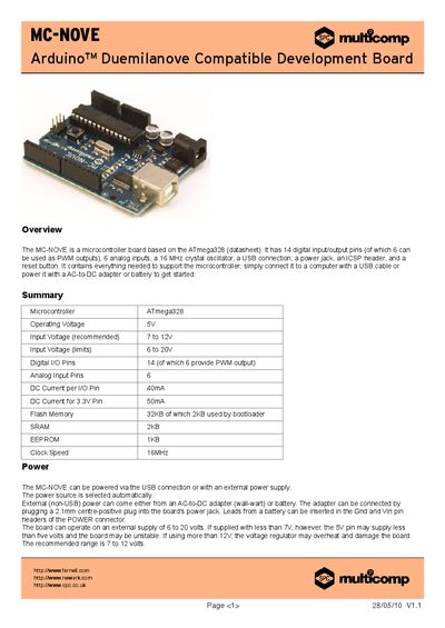
The MC-NOVE development board is based on the ATmega328 microcontroller and provides 14 digital I/O pins (6 PWM), 6 analog inputs, a 16 MHz crystal, USB connectivity, a power jack, an ICSP header, and a reset button. It includes all necessary components to run the microcontroller and can be programmed with the Arduino IDE.
Power can be supplied via the USB connector or an external 6‑20 V source (recommended 7‑12 V). The board automatically selects the appropriate source. It also features a resettable polyfuse for USB over‑current protection and optional auto‑reset circuitry that can be disabled by cutting a trace or adding a resistor.
| Microcontroller | ATmega328 |
|---|---|
| Operating Voltage | 5 V |
| Recommended Input Voltage | 7 V to 12 V |
| Input Voltage Limits | 6 V to 20 V |
| Digital I/O Pins | 14 (6 PWM) |
| Analog Input Pins | 6 |
| DC Current per I/O Pin | 40 mA |
| DC Current for 3.3 V Pin | 50 mA |
| Flash Memory | 32 KB (2 KB bootloader) |
| SRAM | 2 KB |
| EEPROM | 1 KB |
| Clock Speed | 16 MHz |
| Board Dimensions | 2.7 in × 2.1 in |
| Pin Spacing (pins 7‑8) | 160 mil (0.16 in) |
It can be powered via the USB connection or an external power supply of 6 V to 20 V (recommended 7 V‑12 V); the board automatically selects the source.
Each digital I/O pin can provide up to 40 mA of current.
By cutting the trace labelled "RESET-EN" or soldering the pads together, or by adding a 110 Ω resistor from 5 V to the reset line.