
The LMS1487 is a low power differential bus/line transceiver designed for high speed bidirectional data communication on multipoint bus transmission lines. It meets ANSI Standards TIA/EIA RS422-B, TIA/EIA RS485-A and ITU recommendation and V.11 and X.27. The LMS1487 combines a TRI-STATE™ differential line driver and differential input receiver, both of which operate from a single 5.0V power supply. The driver and receiver have an active high and active low, respectively, that can be externally connected to function as a direction control. The driver and receiver differential inputs are internally connected to form differential input/output (I/O) bus ports that are designed to offer minimum loading to bus whenever the driver is disabled or when VCC = 0V. These ports feature wide positive and negative common mode voltage ranges, making the device suitable for multipoint applications in noisy environments. The LMS1487 is available in a 8-Pin SOIC and 8-pin DIP packages. It is a drop-in socket replacement to Maxim’s MAX1487.
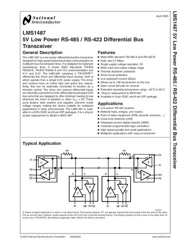
The LMS1487 is a low‑power 5 V differential bus transceiver that meets ANSI RS‑485‑A and RS‑422‑B standards. It provides a tri‑state driver, short‑circuit protection, and an open‑circuit fail‑safe receiver, making it suitable for noisy multipoint applications such as LANs, industrial PLCs, and point‑of‑sale equipment. The device operates from a single 5 V supply, draws only 320 µA quiescent current, and can support up to 128 transceivers on a single bus.
The datasheet details electrical characteristics, pin descriptions, ordering information, and typical performance graphs. It lists the available 8‑pin SOIC and 8‑pin DIP packages, absolute maximum ratings, and physical dimensions. Application notes describe required terminating and biasing resistors for reliable bus operation.
| Supply Voltage (Vcc) | 4.75 V – 5.25 V |
|---|---|
| Data Rate | 2.5 Mbps |
| Operating Temperature Range | -40 °C to 85 °C |
| Quiescent Current | 320 µA |
| Maximum Bus Nodes | 128 transceivers |
| Package Types | 8‑pin SOIC and 8‑pin DIP |
| Input Voltage Range (DI, DE, RE) | ~0.3 V to Vcc + 0.3 V |
The LMS1487 supports a data rate of up to 2.5 Mbps.
Up to 128 LMS1487 transceivers can share a single bus.
It operates from a single 5 V supply, with a permissible range of 4.75 V to 5.25 V.
The device is offered in 8‑pin SOIC and 8‑pin DIP packages.