
The LM2722 is a high-speed synchronous/asynchronous MOSFET driver designed for use with multi-phase controllers. It differs from the LM2726 by changing the functionality of the SYNC_EN pin to control between synchronous and asynchronous operations. The LM2722 simultaneously drives both top and bottom MOSFETs with a typical 20ns dead time and built-in cross-conduction protection circuitry. Asynchronous operations can be more efficient at very light loads, making it advantageous in portable systems. Each driver of the LM2722 can handle a peak sourcing and sinking current of 3A, and the minimum pulse width is as low as 55ns.
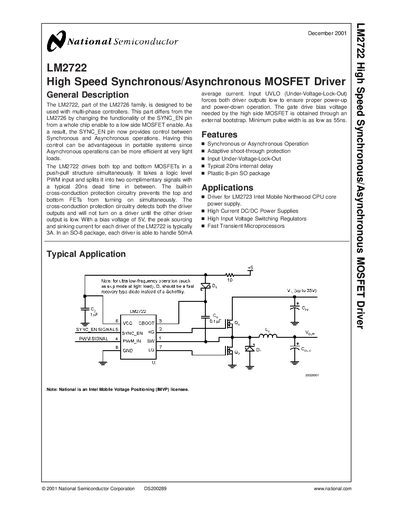
The LM2722 MOSFET driver provides push‑pull control of top and bottom MOSFETs with a selectable SYNC_EN pin for synchronous or asynchronous operation. It accepts a logic‑level PWM input, splits it into complementary outputs, and includes adaptive shoot‑through protection and under‑voltage lock‑out.
Typical applications include Intel mobile CPU core power supplies, high‑current DC‑DC converters, and high‑input‑voltage switching regulators. The device is supplied in an 8‑lead SO package with detailed pin functions and electrical characteristics for design integration.
| Typical Internal Delay | 20 ns |
|---|---|
| Minimum Pulse Width | 55 ns |
| Maximum Power Dissipation | 0.7 W |
SYNC_EN selects low‑side MOSFET enable and switches between synchronous and asynchronous operation.
The PWM_IN pulses must be longer than 55 ns for the shoot‑through protection to work correctly.
The driver provides a typical 20 ns dead time between the complementary outputs.
The device can dissipate up to 0.7 W under the specified thermal conditions.