
The MAX2511 is a complete, highly integrated IF transceiver for applications employing a dual-conversion architecture. Alternatively, the MAX2511 can be used as a single-conversion transceiver if the RF operating frequency ranges from 200MHz to 440MHz. In a typical application, the receiver downconverts a high IF/RF (200MHz to 440MHz) to a 10.7MHz low IF using an image-reject mixer. Functions include an image-reject downconverter with 34dB of image suppression followed by an IF buffer that can drive an off-chip IF filter; an on-chip limiting amplifier offering 90dB of monotonic received-signal-strength indication (RSSI); and a robust limiter output driver. The transmit image-reject mixer generates a clean output spectrum to minimize filter requirements. It is followed by a 40dB variable-gain amplifier that maintains IM3 levels below -35dBc. Maximum output power is 2dBm. A VCO and oscillator buffer for driving an external prescaler are also included. The MAX2511 operates from a 2.7V to 5.5V supply and includes flexible power-management control. For applications using in-phase (I) and quadrature (Q) baseband architecture for the transmitter, Maxim offers a corresponding transceiver product: the MAX2510. The MAX2510 has features similar to those of the product in this document.
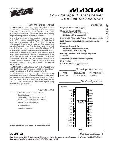
The Maxim MAX2511 is a complete IF transceiver designed for dual‑conversion architectures, supporting RF frequencies from 200 MHz to 440 MHz. It includes an image‑reject downconverter, on‑chip limiting amplifier with 90 dB monotonic RSSI, and a 40 dB variable‑gain amplifier for the transmit path.
The device operates from a 2.7 V to 5.5 V supply, offers a shutdown current of only 0.1 µA, and provides up to 2 dBm of output power. It also features an on‑chip VCO, oscillator buffer, and flexible power‑management modes.
| Operating Voltage Range | 2.7 V to 5.5 V |
|---|---|
| Shutdown Supply Current | 0.1 µA |
| Maximum Output Power | 2 dBm |
| Image Rejection (downconverter) | 34 dB |
| Variable‑Gain Amplifier Range | 40 dB |
| RSSI Dynamic Range | 90 dB |
It operates from a 2.7 V to 5.5 V supply.
The maximum output power is 2 dBm.
In shutdown mode the supply current is reduced to 0.1 µA.
The downconverter provides 34 dB of image rejection.