
Explains how to use the Vivitar 283 light sensor socket to control the flash unit's discharge and duration
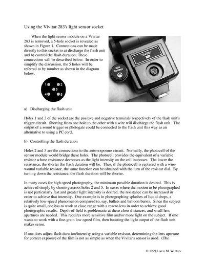
This guide explains how to access the 5‑hole socket revealed when the light‑sensor module is removed from a Vivitar 283 flash. It describes how holes 1 and 3 connect to the flash‑unit trigger circuit for discharging, and how holes 2 and 5 connect to the auto‑exposure circuit for adjusting flash duration.
The document also provides practical methods for selecting lens aperture and estimating flash duration when a variable resistor replaces the photocell, including empirical formulas for ISO 100 film at a 1 m distance.
| Socket hole 2 and 5 function | Connections to the auto‑exposure circuit |
|---|---|
| Lens f‑stop (ISO 100, 1 m) | Add 2 to resistance (kΩ) |
| Flash duration (R 2–100 kΩ) | t = 17 – R µs |
| Minimum flash duration (R <2 kΩ) | ≈20 µs |
Short a wire between holes 1 and 3, which are the positive and negative terminals of the flash‑unit trigger circuit.
Short holes 2 and 5 together, or replace the photocell with a variable resistor and turn it down to lower resistance.
For resistances between 2 kΩ and 100 kΩ, flash duration t (µs) ≈ 17 – R, where R is in kilohms.
Add 2 to the resistance value (in kΩ) to obtain the appropriate f‑stop.