
The MC100LVEP111 is a low skew 1-to-10 differential driver, designed with clock distribution in mind, accepting two clock sources into an input multiplexer. The PECL input signals can be either differential or single-ended (if the VBB output is used). HSTL inputs can be used when the LVEP111 is operating under PECL conditions. The LVEP111 specifically guarantees low output-to-output skew. Optimal design, layout, and processing minimize skew within a device and from device to device. To ensure tightest skew, both sides of differential outputs identically terminate into 50 ohms even if only one output is being used. If an output pair is unused, both outputs may be left open (unterminated) without affecting skew. The MC100LVEP111, as with most other ECL devices, can be operated from a positive VCC supply in PECL mode. This allows the LVEP111 to be used for high performance clock distribution in +3.3 V or +2.5 V systems. Single-ended CLK input operation is limited to a VCC ≥ 3.0 V in PECL mode, or VEE ≤ -3.0 V in NECL mode. Designers can take advantage of the LVEP111's performance to distribute low skew clocks across the backplane or the board. In a PECL environment, series or Thevenin line terminations are typically used as they require no additional power supplies. For more information
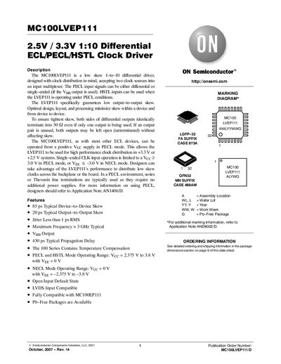
The MC100LVEP111 is a low‑skew 1‑to‑10 differential driver designed for clock distribution. It accepts two clock sources, provides PECL, HSTL and NECL operation modes, and guarantees low device‑to‑device and output‑to‑output skew. Proper 50 Ω termination on both differential outputs is required for optimal performance.
The device offers typical propagation delay of 430 ps, jitter under 1 ps RMS, and supports frequencies up to >3 GHz. It is available in LQFP‑32 and QFN‑32 packages, operates from 2.5 V or 3.3 V supplies in PECL/HSTL mode, and from 0 V with negative supplies in NECL mode. Detailed electrical specifications, package dimensions, and ordering information are provided.
| Typical Device‑to‑Device Skew | 85 ps |
|---|---|
| Typical Output‑to‑Output Skew | 20 ps |
| Jitter (RMS) | <1 ps |
| Maximum Frequency | >3 GHz |
| Typical Propagation Delay | 430 ps |
| Operating Temperature Range | -40 °C to +85 °C |
It operates in PECL/HSTL mode with Vcc from 2.375 V to 3.8 V (Veg = 0 V) and in NECL mode with Vcc = 0 V and Veg from –2.375 V to –3.8 V.
Both sides of the differential outputs should be terminated into 50 Ω, even if only one output is used.