
The FGH30N6S2D / FGP30N6S2D / FGB30NS2D are 600V, SMPS II Series N-Channel IGBTs with Anti-Parallel StealthTM Diode. These LGC devices shorten delay times, and reduce the power requirement of the gate drive. These devices are ideally suited for high voltage switched mode power supply applications where low conduction loss, fast switching times and UIS capability are essential. SMPS II LGC devices have been specially designed for: • Power Factor Correction (PFC) circuits • Full bridge topologies • Half bridge topologies • Push-Pull circuits • Uninterruptible power supplies • Zero voltage and zero current switching circuits
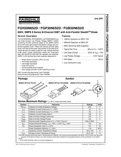
This handbook provides the specifications, electrical characteristics, and handling guidelines for the Fairchild FGH30N6S2D, FGP30N6S2D, and FGB30N6S2D 600 V SMPS II series IGBTs. It includes package information, performance curves, and recommended operating conditions.
The document also contains safety precautions for ESD protection, typical switching performance, and trademark information for Fairchild Semiconductor products.
| Collector‑Emitter Breakdown Voltage (BVces) | 600 V |
|---|---|
| Continuous Collector Current (25 °C) | 45 A |
| Continuous Collector Current (110 °C) | 20 A |
| Pulsed Collector Current | 108 A |
| Gate‑to‑Emitter Voltage (Continuous) | +20 V |
| Gate‑to‑Emitter Voltage (Pulsed) | +30 V |
| Power Dissipation (Total, 25 °C) | 167 W |
| Typical Fall Time at 125 °C | 90 ns |
The device’s collector‑emitter breakdown voltage is rated at 600 V.
The typical fall time is 90 ns when the junction temperature is 125 °C.
All leads should be kept shorted together before assembly to prevent electrostatic discharge.
The maximum continuous collector current at 25 °C is 45 A.