
MAX5976B Evaluation Board is a verified design for evaluating the MAX5976B, a hot-swap controller with an integrated 7A MOSFET. The evaluation board is configured for 2.7V to 18V hot-swap applications with current up to 7A, providing a fully integrated solution. The evaluation board uses the MAX5976BETE+ in a 5mm*5mm*0.8mm, 16-lead, TQFN package, and is a verified 4-layer PCB design. By replacing the U1 device, the evaluation board can also be used to evaluate the MAX5976A.
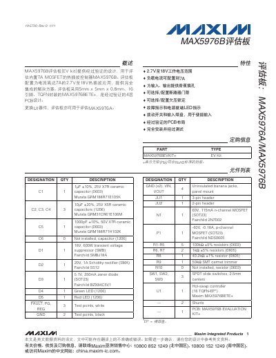
The Maxim MAX5976B Evaluation Kit provides a fully‑tested reference design for evaluating the MAX5976B hot‑swap controller with an integrated 7 A MOSFET. The board supports a 2.7 V – 18 V input range and delivers up to 7 A of load current, making it suitable for hot‑swap applications.
The document describes the component list, default jumper and switch positions, test procedures, and includes the schematic and PCB layout diagrams. It also explains how to configure the current‑limit and undervoltage‑lockout thresholds by adjusting jumpers JU1, JU2 and the associated resistors.
| Input voltage range | 2.7 V to 18 V |
|---|---|
| Controller package | 5 mm × 5 mm × 0.8 mm 16‑pin TQFN |
| PCB layers | 4‑layer design |
The kit operates from 2.7 V up to 18 V.
Set jumper JU1 to position 1‑2 (connected to resistor R8) which configures the current limit to 7 A.
Install jumper JU2 to connect ON1 to VIN through resistors R1 and R10; set SW1 to position 1‑2 before installing the shunt.