
The MAX1700/MAX1701 are high-efficiency, low-noise, step-up DC-DC converters intended for use in battery-powered wireless applications. They use a synchronous-rectified pulse-width-modulation (PWM) boost topology to generate 2.5V to 5.5V outputs from battery inputs such as one to three NiCd/NiMH cells or one Li-Ion cell. Both devices have an internal 1A, 130mΩ N-channel MOSFET switch and a 250mΩ P-channel synchronous rectifier. With their internal synchronous rectifier, the MAX1700/MAX1701 deliver 5% better efficiency than similar non-synchronous converters. They also feature a pulse-frequency-modulation (PFM) standby mode to improve efficiency at light loads, and a 3µA shutdown mode. The MAX1700/MAX1701 come in 16-pin QSOP packages (which occupy the same space as an 8-pin SO). The MAX1701 includes two comparators to generate power-good and low-battery warning outputs. It also contains a gain block that can be used to build a linear regulator using an external P-channel pass device. For higher-power outputs, refer to the MAX1703. For dual outputs (step-up and linear regulator), refer to the MAX1705/MAX1706. For an on-board analog-to-digital converter, refer to the MAX848/MAX849. The MAX1701 evaluation kit is available to speed design time. Applications include digital cordless phones, personal communicators, PCS phones, palmtop computers, wireless handsets, hand-held instruments, and two-way pagers. Features include up to 96% efficiency, 1.1V IN guaranteed start-up, 0.15 mA standby current, and 3 µA shutdown current.
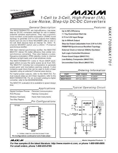
The MAX1700 and MAX1701 converters provide up to 96 % efficiency while delivering up to 800 mA output from a 0.7 V‑5.5 V input range. They use a synchronous‑rectified PWM/PMF topology with an internal 1 A N‑channel MOSFET and a 250 mΩ P‑channel rectifier, offering low‑noise operation and a 3 µA shutdown current.
The devices are supplied in a 16‑pin QSOP package and include features such as a power‑good comparator, low‑battery warning, and a gain block for linear‑regulator applications. Typical applications include digital cordless phones, handheld instruments, and other battery‑powered wireless equipment.
| Input voltage range | 0.7 V – 5.5 V |
|---|---|
| Adjustable output voltage | 2.5 V – 5.5 V |
| Maximum output current | 800 mA |
| Efficiency | up to 96 % |
| Shutdown current | 3 µA |
| Package | 16‑pin QSOP |
The converters operate from 0.7 V up to 5.5 V input.
They can supply up to 800 mA of output current.
They achieve up to 96 % efficiency.
Both devices are supplied in a 16‑pin QSOP package.