
The MAX6620 is a four-channel linear voltage output driver for controlling fans. It directly controls the fan drive voltages via the I2C interface. Each output drives the base of an external bipolar transistor or the gate of a FET in high-side drive configuration. Voltage feedback at the fan’s power-supply terminal is used to force the correct out- put voltage. The MAX6620 offers two methods for fan control. In RPM mode, the MAX6620 monitors four fan tachometer logic outputs for precise (±1%) control of fan RPM and detection of fan failure. In DAC mode, each fan is dri- ven with a voltage resolution of 9 bits and the tachome- ter outputs of the fans are monitored for failure. The DAC_START input selects the fan power-supply voltage at startup to ensure appropriate fan drive when power is first applied. A watchdog feature turns the fans fully on to protect the system if there are no valid I2C communications within a preset timeout period. The MAX6620 operates from a 3.0V to 5.5V power sup- ply with low 250µA supply current, and the I2C-compati- ble interface makes it ideal for fan control in a wide range of cooling applications. The MAX6620 is avail- able in a 28-pin TQFN package and operates over the -40°C to +125°C automotive temperature range.
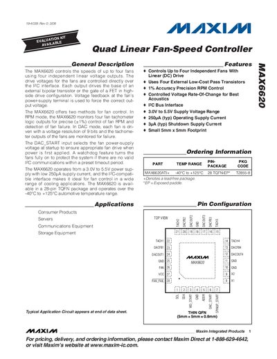
The MAX6620 controls the speeds of up to four fans using four independent linear voltage outputs. Fan drive voltages are set via an I²C‑compatible serial interface, with options for RPM‑mode monitoring or DAC‑mode voltage control. The device includes a watchdog, spin‑up control, and fan‑failure detection.
The datasheet provides absolute maximum ratings, electrical characteristics, pin descriptions, and package dimensions for the 28‑pin TQFN version. It also lists typical operating parameters such as supply voltage range, current consumption, timing specifications, and accuracy figures for fan control.
| Operating Supply Voltage | 3.0 V to 5.5 V |
|---|---|
| Operating Supply Current (typical) | 0.25 mA |
| Shutdown Supply Current (typical) | 3 µA |
| Drive Voltage Resolution | 9 bits |
| Maximum Fan Count | 4 |
| Operating Temperature Range | -40 °C to +125 °C |
| Package Type | 28‑pin TQFN |
| I²C Clock Frequency | up to 400 kHz |
| Standby Supply Current (typical) | 3 µA |
It can control up to four independent fans.
The device operates from 3.0 V to 5.5 V.
The I²C interface works up to 400 kHz.
Typical standby current is about 3 µA.