
The MAX1964/MAX1965 power-supply controllers are designed to address cost-sensitive applications demanding voltage sequencing/tracking, such as cable modem consumer premise equipment (CPE), xDSL CPE, and set-top boxes. Operating off a low-cost, unregulated DC supply (such as a wall adapter output), the MAX1964 generates three positive outputs and the MAX1965 generates four positive outputs and one negative output to provide an inexpensive system power supply. The MAX1964 includes a current-mode synchronous step-down controller and two positive regulator gain blocks. The MAX1965 has one additional positive gain block and one negative regulator gain block. The main synchronous step-down controller generates a high- current output that is preset to 3.3V or adjustable from 1.236V to 0.75 ✕ VIN with an external resistive-divider. The 200kHz operating frequency allows the use of low- cost aluminum-electrolytic capacitors and low-cost power magnetics. Additionally, the MAX1964/MAX1965 step-down controllers sense the voltage across the low- side MOSFET’s on-resistance to efficiently provide the current-limit signal, eliminating the need for costly cur- rent-sense resistors. The MAX1964/MAX1965 generate additional supply rails at low cost. The positive regulator gain blocks use an external PNP pass transistor to generate low voltage rails directly from the main step-down converter (such as 2.5V or 1.8V from the main 3.3V output) or higher voltages using coupled w
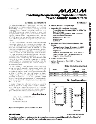
The MAX1964 and MAX1965 are power‑supply controllers designed for cost‑sensitive applications such as cable modems, xDSL CPE, and set‑top boxes. They operate from a low‑cost unregulated DC source and provide multiple regulated output rails with voltage sequencing (MAX1964) or tracking (MAX1965).\n\nKey features include a 200 kHz synchronous step‑down converter, adjustable output voltages, a power‑good indicator, and high efficiency (up to 95%). The datasheet provides absolute maximum ratings, detailed electrical characteristics, pin descriptions, typical operating curves, and package information.
| Input voltage range | 4.5 V to 28 V |
|---|---|
| Number of outputs (MAX1964) | Three positive outputs |
| Number of outputs (MAX1965) | Four positive and one negative output |
| Switching frequency | 200 kHz |
| Efficiency | up to 95 % |
| Operating temperature range | -40 °C to +85 °C |
The controllers accept an input voltage from 4.5 V up to 28 V.
MAX1965 provides four positive output rails and one negative output rail.
Both devices operate at a fixed 200 kHz switching frequency.
Yes, a power‑good (POK) output is provided to monitor regulation status.