
This datasheet provides detailed information on the features and characteristics of the TLE6280GP 3-phase bridge driver IC. The IC features multiple protection functions and is dedicated to 3-phase high current motor bridges in PWM control mode. The device fulfills requirements in automotive 12V applications.
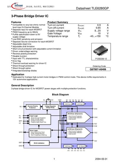
The TLE6280GP is a 3‑phase bridge driver IC designed for high‑current motor drives in automotive applications such as cooling fans, water pumps, and power steering. It supports supply voltages from 8 V up to 40 V and can operate down to 9 V, providing reliable gate drive for external MOSFETs.
Key functional blocks include separate high‑side and low‑side drivers with bootstrap capacitors, an internal charge‑pump regulator, and programmable pins for dead‑time, shoot‑through protection, and current limitation. The device also offers error detection via an open‑collector ERR pin and a multi‑function MFP pin for reset, short‑circuit level adjustment, and shoot‑through deactivation.
| Turn‑on current | 0.9 A |
|---|---|
| Turn‑off current | 0.85 A |
| Supply voltage range | 8.20 V |
| PWM frequency | up to 30 kHz |
| Gate voltage | 10 V |
| Operating temperature range | -40 °C … +150 °C |
| Package | P‑DSO36‑12 |
The device operates from 8.20 V and can be used over a supply range of 8 V to 40 V.
Dead time is set by adding an external resistor from the DT pin to ground, allowing a range from 100 ns to 4 µs.