
This document introduces the features and characteristics of XMEGA DAC in the AVR1508 Xplain training, including configuration options and functionality, conversion triggers, and single and dual channel operation.
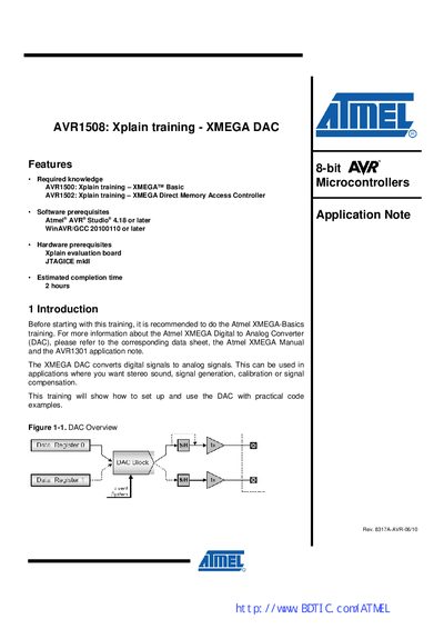
The AVR1508 training document introduces the Atmel XMEGA DAC, describing its conversion triggers, single‑ and dual‑channel operation, and left/right adjusted value handling. It includes practical tasks that guide users through setting up the DAC, generating waveforms, and using the event system and DMA.
Four hands‑on tasks cover DAC introduction, single‑conversion mode, dual‑conversion mode, and using the event system. Each task provides code examples, wiring details, and troubleshooting tips, along with references to the XMEGA A Manual and related datasheets.
| Input resolution | 12‑bit |
|---|---|
| Register size | two 8‑bit registers (high and low) |
| Sample rate example | 11 kSps |
| Sample rate for task 2 | 11 000 samples per second |
| Minimum output resistor | 1 kΩ minimum |
| Number of DAC modules | 2 (DACA and DACB) |
| Channels per module | 2 |
| Refresh interval generator | automatic refresh interval generator |
The DAC module contains two data channels with corresponding data registers.
A conversion can be triggered either by writing to the data registers or by an incoming event from the Atmel XMEGA Event System.
Right‑adjusted values are the default; left‑adjusted values can be selected via the LEFTADJ bit.
AVCC is chosen as the voltage reference by default.