
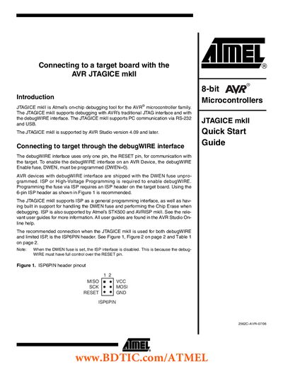
JTAGICE mkII is Atmel's on-chip debugging tool for the AVR® microcontroller family. It supports debugging with AVR's traditional JTAG interface and with the debugWIRE interface. The JTAGICE mkII supports PC communication via RS-232 and USB. It is supported by AVR Studio version 4.09 and later. When connecting to the target board through the debugWIRE interface, only the RESET pin is used for communication. To enable the debugWIRE interface on an AVR Device, the debugWIRE Enable fuse, DWEN, must be programmed (DWEN=0). AVR devices with debugWIRE interface are shipped with the DWEN fuse unprogrammed. ISP or High-Voltage Programming is required to enable debugWIRE. Programming the fuse via ISP requires an ISP header on the target board. Using the 6-pin ISP header as shown in Figure 1 is recommended. The JTAGICE mkII supports ISP as a general programming interface, as well as having built-in support for handling the DWEN fuse and performing the Chip Erase when debugging. ISP is also supported by Atmel's STK500 and AVRISP mkII. See the relevant user guides for more information. All user guides are found in the AVR Studio Online help. The recommended connection when the JTAGICE mkII is used for both debugWIRE and limited ISP is the ISP6PIN header. See Figure 1, Figure 2 on page 2, and Table 1 on page 2.
The JTAGICE mkII is Atmel’s on‑chip debugging tool for AVR microcontrollers. It supports the traditional JTAG interface, the debugWIRE interface, and can communicate with a PC via RS‑232 or USB. The guide explains how to connect the probe to a target board using the appropriate headers and pins.
Key topics include enabling debugWIRE, using the ISP header, wiring the JTAG signals, power requirements, and setting up the tool with AVR Studio. The document also lists the supported devices and provides safety notes for the RESET line.
| Supported communication interfaces | RS-232 and USB |
|---|---|
| Power supply voltage | 9 to 12 V |
| debugWIRE pull‑up resistor minimum | 10 kΩ |
A JTAG connection requires six pins: TCK, TDO, TDI, TMS, VTref and GND.
When using the RS‑232 cable the probe needs an external 9‑12 V supply; a USB connection provides power without an external supply.