
This document introduces the features and characteristics of the ATmega162 microcontroller, including high performance, low power, high endurance non-volatile memory segments, JTAG (IEEE std. 1149.1 Compliant) interface, boundary scan capabilities, extensive on-chip debug support, two 8-bit timers/counters, one 16-bit timer/counter, real time counter, four PWM channels, 8-channel, 10-bit ADC 8 single-ended channels 7 differential channels in TQFP package only 2 differential channels with programmable gain(1x, 10x or 200x), byte-oriented two-wire serial interface, programmable serial USART, master/slave SPI serial interface, programmable watchdog timer
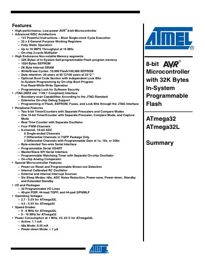
The ATmega32 and ATmega32L are low‑power 8‑bit CMOS microcontrollers based on the AVR enhanced RISC architecture. They offer up to 32 Kbytes of In‑System Programmable Flash, 1 Kbyte EEPROM, 2 Kbyte SRAM, multiple timers, an 8‑channel 10‑bit ADC and extensive peripheral options.
This handbook includes a feature summary, pin‑out diagrams, register maps, electrical characteristics, power‑consumption data, packaging information and errata. It serves as a reference for designers implementing the device in embedded applications.
| Flash memory | 32 Kbytes |
|---|---|
| EEPROM | 1 Kbyte |
| SRAM | 2 Kbytes |
| Operating voltage (ATmega32L) | 2.7 V – 5.5 V |
| Operating voltage (ATmega32) | 4.5 V – 5.5 V |
| Maximum clock speed (ATmega32L) | 0 – 8 MHz |
| Maximum clock speed (ATmega32) | 0 – 16 MHz |
| Active current (1 MHz, 3 V, ATmega32L) | 1.1 mA |
| Idle current (1 MHz, 3 V, ATmega32L) | 0.35 mA |
| Power‑down current (ATmega32L) | < 1 nA |
The ATmega32 provides 32 Kbytes of In‑System Programmable Flash memory.
The ATmega32L operates from 2.7 V to 5.5 V.
Typical active current is about 1.1 mA.