
The AD9822 is a complete analog signal processor for CCD imaging applications. It features a 3-channel architecture designed to sample and condition the outputs of trilinear color CCD arrays. Each channel consists of an input clamp, correlated double sampling, 1-6× programmable gain, and ±350 mV programmable offset, among other features.
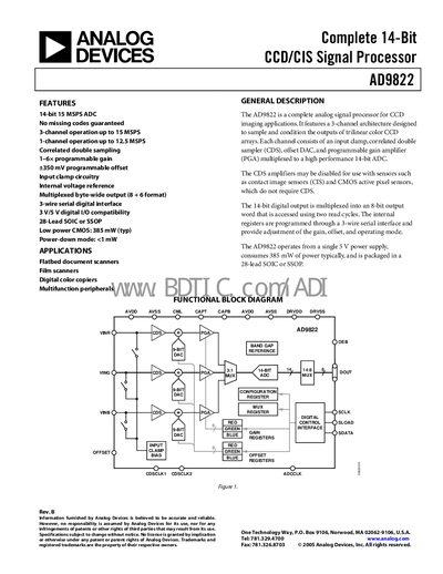
The AD9822 is a complete analog signal processor for CCD imaging applications. It provides a 3‑channel architecture with programmable gain, offset, and a high‑performance 14‑bit ADC, supporting both 3‑channel (up to 15 MSPS) and 1‑channel (up to 12.5 MSPS) operation.
The device operates from a single 5 V supply, consumes about 385 mW in typical 3‑channel mode, and is offered in a 28‑lead SOIC or SSOP package. It includes input clamp circuitry, an internal voltage reference, and a 3‑wire serial digital interface for register programming.
| Maximum conversion rate (3‑channel CDS) | 15 MSPS |
|---|---|
| Maximum conversion rate (1‑channel CDS) | 12.5 MSPS |
| ADC resolution | 14 bits |
| Typical power dissipation (3‑channel mode) | 385 mW |
| Input signal range (differential) | 2.0 Vp‑p |
| Analog supply voltage (AVDD) | 5.0 V typical |
The AD9822 can convert at up to 15 MSPS in 3‑channel CDS mode and up to 12.5 MSPS in 1‑channel CDS mode.
The serial interface uses SCLK (clock), SDATA (data I/O) and SLOAD (load pulse) pins.