
This document describes the features and characteristics of the PS21961-ST integrated power module, including its low-loss 600V/3A RC-IGBT inverter bridge, N-side three-phase output, and DC-to-AC power conversion. The module is designed for AC100V~200V inverter drive for small power motor control.
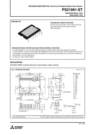
The PS21961-ST is a dual‑in‑line package (DIP) intelligent power module that integrates IGBT switches, drive circuits, and protection functions for three‑phase AC inverter applications. It is designed for AC100‑200 V inverter drives for small power motor control.
The manual includes maximum ratings, electrical and thermal characteristics, mechanical data, recommended operating conditions, wiring diagrams, timing charts for protection functions, and example application circuits. It also gives guidance on mounting, heat‑sink attachment, and component selection to ensure reliable operation.
| Supply voltage (Veco) | 450 V |
|---|---|
| Collector‑emitter voltage (VCES) | 600 V |
| IGBT collector current (continuous) | 3 A |
| Mounting torque (M3 screw) | 0.69 N·m |
| Weight | 10 g |
| Isolation voltage | 1500 V |
Each IGBT can carry a continuous collector current of 3 A at 25 °C.
A torque of 0.69 N·m is recommended for the M3 mounting screw.
The control supply voltage (VD) should be between 13.5 V and 16.5 V, typically 15 V.