
This document provides power dissipation data for the USPN-4. The power dissipation value varies with the mount board conditions. The document includes measurement conditions and the relationship between power dissipation and ambient temperature under specified conditions.
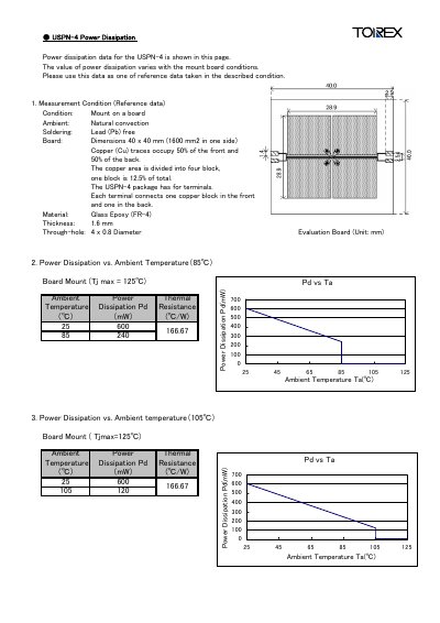
This document provides power‑dissipation data for the USPN‑4 semiconductor device. The data are intended for reference when the device is mounted on a standard board under the conditions described.
Measurement conditions include mounting on a 40 × 40 mm FR‑4 board, natural convection ambient, lead‑free soldering, 1.6 mm board thickness, copper traces covering 50 % of both front and back, and four 0.8 mm through‑hole terminals. Power‑dissipation versus ambient temperature curves are given for 85 °C and 105 °C board‑mount scenarios, with a thermal resistance of 166.67 ℃/W.
| Board dimensions | 40 x 40 mm (1600 mm² per side) |
|---|---|
| Copper trace coverage | 50 % front, 50 % back |
| Package material | Glass Epoxy (FR‑4) |
| Board thickness | 1.6 mm |
| Through‑hole size | 4 × 0.8 mm diameter |
| Thermal resistance | 166.67 ℃/W |
The thermal resistance is 166.67 ℃/W.