
Key facts
- Brand
- YASKAWA
- Model
- V1000
- Category
- Industrial Supply
- Documents
- 5
- Languages
- EN · ZH
- Last added
- 2026-11-05
Start here
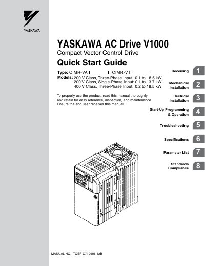
Yaskawa V1000 AC Drive Quick Start Guide
This Quick Start Guide provides essential safety messages, mechanical and electrical installation instructions, and basic programming steps for the Yaskawa V1000 AC Drive. It is intended to help end‑users correctly install, wire, and start up the drive while ensuring compliance with safety standards.
The guide also includes troubleshooting advice, a parameter list, and references to related manuals for more detailed technical information. Revision history and contact details for Yaskawa worldwide offices are provided at the end of the document.
YASKAWA V1000 specifications
| Input voltage (single‑phase) | 200 V |
|---|---|
| Input voltage (three‑phase) | 400 V |
| Recommended main‑circuit wire size | 600 V, 75 °C rated, 2‑type PVC insulated |
All YASKAWA V1000 documents by type
Mounting, wiring and first power-up. Read it before the hardware goes in.
Disassembly, diagnostics and part numbers, for repair.
The shortest path to a working setup, usually only a few pages.
Questions answered in these manuals
What is the model number of the MECHATROLINK-II Option?
The model number is SI-T3/V.
From: Yaskawa V1000 MECHATROLINK-II Option Installation Manual
What safety precaution is required after disconnecting power?
Wait 5 minutes for capacitor discharge before proceeding.
From: Yaskawa V1000 MECHATROLINK-II Option Installation Manual
How can I verify the model and name‑plate of the V1000 inverter?
Refer to section 1.2 which explains the method for checking the inverter’s model number and name‑plate details.
What wire size is recommended for the main circuit connections?
Use 600 V, 75 °C rated PVC insulated wire; the size should keep voltage drop within 2 % of the rated voltage.
What safety information is provided before installing the drive?
The manual begins with a Preface & General Safety section and includes safety messages, drive‑label warnings, and safety symbols throughout the document.
How are the protective covers removed and installed?
Follow the IP20/Open‑Chassis Cover Removal and Installation procedure described in the Mechanical Installation chapter.