
Key facts
- Brand
- UNITRODE
- Model
- UC5
- Industry
- Industrial
- Documents
- 2
- Languages
- EN
- Last added
- 2012-08-08
Start here
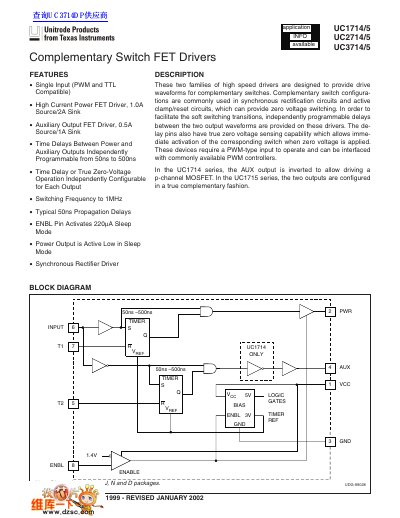
Unitrode UC1714/5 UC2714/5 UC3714/5 Complementary Switch FET Drivers Datasheet
The document describes three families of high-speed driver circuits (UC1714/5, UC2714/5, and UC3714/5) designed to provide drive waveforms for complementary switches in synchronous rectification and active clamp/reset circuits. These devices feature independently programmable time delays between power and auxiliary outputs ranging from 50ns to 500ns.
Read onlineUNITRODE UC5 specifications
| Supply Voltage (VCC) | 7 to 20 V |
|---|---|
| Auxiliary Driver Source Current (Peak) | 0.54A |
| Time Delay Range | 50ns to 500ns |
| Switching Frequency | to 1MHz |
Source: Unitrode UC1714/5 UC2714/5 UC3714/5 Complementary Switch FET Drivers Datasheet
All UNITRODE UC5 documents by type
Ratings, dimensions and ordering codes, for selection and design work.
Questions answered in these manuals
What is the operating junction temperature range for UC1714/5?
The operating junction temperature range is -65°C to 150°C.
From: Unitrode UC1714/5 UC2714/5 UC3714/5 Complementary Switch FET Drivers Datasheet
What happens when the ENBL pin is low?
The device enters sleep mode, and the power output becomes active low.
From: Unitrode UC1714/5 UC2714/5 UC3714/5 Complementary Switch FET Drivers Datasheet
What is the operating junction temperature for UC1714/5?
The operating junction temperature range is -65°C to 150°C.
From: Unitrode UC1714/5, UC2714/5, UC3714/5 Complementary Switch FET Drivers Datasheet
What happens when the ENBL pin is low?
The device enters sleep mode, and the power output becomes active low.
From: Unitrode UC1714/5, UC2714/5, UC3714/5 Complementary Switch FET Drivers Datasheet