
Rockwell Automation Kinetix 5700 Power Module Installation Guide

Installation guide for Rockwell Automation Kinetix 5700 power modules (2198-P031, 2198-P070, 2198-P141, 2198-P208) covering preparation, mounting, and wiring.
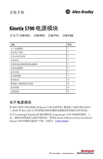

Rockwell Automation Kinetix 5700 Power Module Installation Guide - cover page
Brand
Rockwell Automation
Category
Industrial Robot
Document type
Installation Guide
Language
Chinese
Pages
16
File format
PDF
File size
1.7 MB
Published
13 October, 2026
Updated
13 October, 2026
MD5 checksum
12269F589E4E902C56C14DE9335BD0A9

About this manual

This document provides installation instructions for the Kinetix 5700 Power Module, which supplies continuous output power and current to Kinetix 5700 servo drives with 400 V class three-phase AC input. It covers preparation steps, including removing ground screws for specific power configurations, and details the mounting process on a panel. This manual is written in Chinese.

What's inside

  • Important User Notices
  • Product Catalog Number Description
  • Preparation
  • Removing Ground Screws
  • Installing Power Module
  • Drilling Layout
  • Connector Data
  • Wiring Requirements
  • Breaker/Fuse Technical Data
  • Technical Specifications

Specifications

Input Voltage324...528 V rms, three-phase
Minimum Cabinet Depth300 mm

Frequently asked questions

Do I need to remove ground screws for a grounded Y-type power configuration?

No, you do not need to remove the screws if using a grounded Y-type power distribution system.

What is the maximum tightening torque for the M5 steel bolts?

The maximum tightening torque is 4.0 N•m (35.4 lb•in).

Download PDF (1.7 MB)

More Rockwell Automation Manuals


View all Rockwell Automation manuals →