
Installation guide for Rockwell Automation POINT I/O 1734-IB2/IB4/IB8 input modules, covering mounting, wiring, safety and specifications.
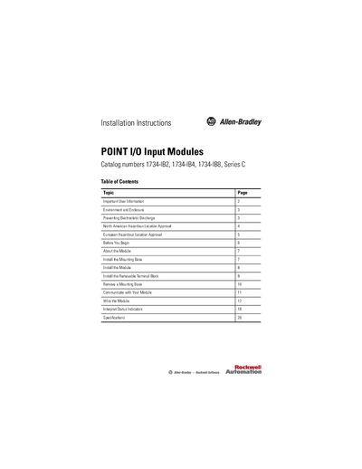
This guide provides safety and environmental information for the POINT I/O input modules, including electrostatic discharge protection and hazardous‑location approvals. It explains the required enclosure ratings, grounding, and handling precautions.
The document walks through installing the mounting base, the module, and the removable terminal block, as well as wiring, status indicator interpretation, and key specifications such as voltage, current and input impedance.
| Inputs per module | 2 (IB2), 4 (IB4), 8 (IB8) |
|---|---|
| Voltage on‑state minimum | 10 V DC |
| Voltage on‑state nominal | 24 V DC |
| Voltage on‑state maximum | 28.8 V DC |
| Current on‑state minimum | 2 mA |
| Current on‑state nominal | 4 mA @ 24 V DC |
| Input impedance nominal | 3.6 kΩ |
| Terminal base screw torque | 0.8 Nm (7 lb‑in.) |
The minimum on‑state voltage is 10 V DC.
The terminal base screw should be tightened to 0.8 Nm (7 lb‑in.).