
Installation guide for Rockwell Automation Kinetix 5700 DC bus power supplies (2198-P031, P070, P141, P208), covering preparation, mounting, wiring, and…
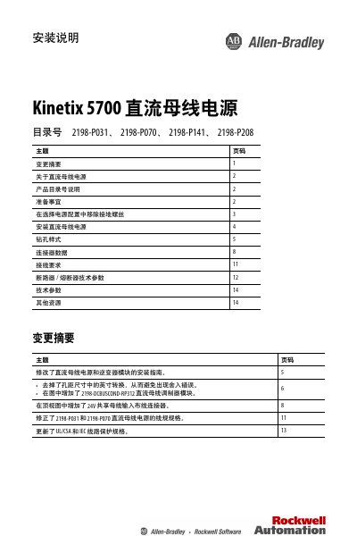
This document provides installation instructions for the Kinetix 5700 DC bus power supply, covering models 2198-P031, 2198-P070, 2198-P141, and 2198-P208. It details preparation steps, including the removal of grounding screws for specific power configurations, and outlines the physical installation process within a control cabinet. This manual is written in Chinese.
| Continuous Output Power (2198-P031) | 0.5 kW |
|---|---|
| Continuous Output Current (2198-P031) | 10.5 A |
| Continuous Output Power (2198-P070) | 25.5 kW |
| Continuous Output Current (2198-P070) | 37.3 A |
| Continuous Output Power (2198-P141) | 46.9 kW |
| Continuous Output Current (2198-P141) | 69.2 A |
| Continuous Output Power (2198-P208) | 69.2 kW |
| Continuous Output Current (2198-P208) | 105.0 A |
The grounding screw should be removed if using ungrounded, corner-grounded, or impedance-grounded power configurations.
The recommended minimum cabinet depth is 300 mm (11.81 in.).
The maximum tightening torque for the M5 screws is 4.0 N•m (35.4 lb•in).