
User guide for the PN532 NFC RFID module: I2C, SPI and HSU interfaces, Arduino wiring, RFID read/write tests, P2P NFC and Android use.
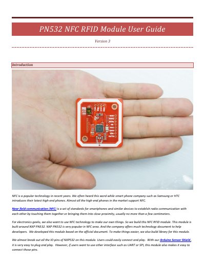
The PN532 NFC RFID Module User Guide (Version 3) covers a module built around the NXP PN532 chip for adding near field communication to hobby projects. It explains what NFC is, lists the features of the V3 hardware such as support for I2C, SPI and HSU interfaces, a built-in PCB antenna and a smaller board size, and shows the toggle-switch settings used to select each interface.
The document then describes hardware installation, including soldering connectors and wiring the module to Arduino UNO, Leonardo, Mega 2560 and Due boards, followed by function tests: reading and writing RFID cards, peer-to-peer communication between two modules over I2C, and communication with an Android phone. A short revision history lists revisions A and B.
| Supply voltage (VCC) | 3.3V~5V |
|---|---|
| I2C/UART level | 3.3V~24V TTL |
| SPI level | 3.3V TTL with 100 ohm resistors in series |
| Communication interfaces | I2C, SPI and HSU (High Speed UART) |
| Default interface mode | HSU |
| Board size | 43mm*41mm*4mm |
| Reading distance | 5~7cm |
| Antenna | Built-in PCB antenna |
| Supported cards | Mifare 1k, 4k, Ultralight and DesFire cards |
Set the small SMD toggle switch on the board. Channel 1 and Channel 2 set to OFF/OFF gives HSU, ON/OFF gives I2C and OFF/ON gives SPI.
HSU (High Speed UART) is the default mode; the I2C and HSU pins are shared.
The communication distance is 5cm to 7cm, up from 4~6 cm on the previous version.
Peer-to-peer communication between two PN532 modules is only supported in I2C mode.