
Parker 514C DC Controller technical manual covering specifications, wiring, installation, commissioning, diagnostics and repair of the 514C range.
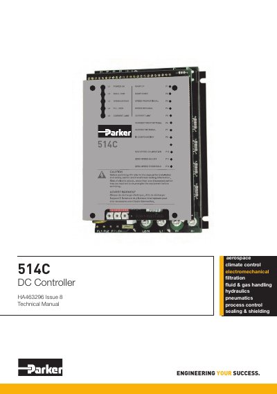
This is the Parker 514C DC Controller Product Manual (HA463296 Issue 8). The 514C is a DC motor speed controller intended for industrial use, mounted inside a protective enclosure and permanently earthed. It controls the speed of a DC shunt wound or permanent magnet motor in all 4 quadrants, operating from a single phase AC mains supply of 110 Vac to 415 Vac at 50 or 60 Hz, with an auxiliary supply for internal power generation and main contactor sequencing. Speed is regulated by a linear closed loop with switch-selectable tachogenerator or armature voltage feedback, and a current loop inside the speed loop keeps motor current at controlled levels.
The manual covers the product range (514C-04, 514C-08, 514C-16 and 514C-32 at 4A, 8A, 16A and 32A DC full load current), the functional comparison with the 540 series, technical specification, EMC ratings and product code. It then gives pre-installation planning with basic wiring diagrams and terminal descriptions, the installation procedure including UL compliance requirements, setting-up and commissioning via option switches and potentiometers, and diagnostics with LEDs, drive trips, test points and troubleshooting, followed by certification, service, repair and disposal.
| Product ratings (DC full load current) | 514C-04: 4A, 514C-08: 8A, 514C-16: 16A, 514C-32: 32A |
|---|---|
| Main supply | Single phase AC, 110 Vac to 415 Vac, 50 or 60 Hz |
| Motor types | DC shunt wound or DC permanent magnet motor |
| Quadrant operation | All 4 quadrants |
| Speed feedback | Tachogenerator or armature voltage, switch selectable |
| Motor protection | Stall detection removes current after approximately 60 seconds |
| Capacitor discharge time | Allow at least 5 minutes for discharge to safe levels (<50V) |
The equipment is intended for industrial motor speed control using DC shunt wound or DC permanent magnet motors.
It operates from a single phase AC mains supply of 110 Vac to 415 Vac at 50 or 60 Hz.
No. It is designed to be functionally equivalent to the 540 series controllers, not a direct replacement; a terminal-to-terminal comparison is included in the manual.
Allow at least 5 minutes for the drive's capacitors to discharge to safe voltage levels below 50V, and confirm this with a suitable meter.