
This document is the user manual for DC1763A. It introduces the function and usage of DC1763A.
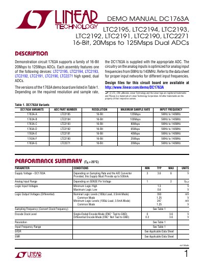
This document provides setup and operation instructions for the DC1763A demonstration circuit, which supports a family of 16-bit ADCs including LTC2195, LTC2194, and others. It details jumper configurations, power requirements, analog input and clock setup, and software use with PScope. The board is designed for evaluating ADC performance with frequencies from 5MHz to 140MHz.
The manual includes quick start procedures, jumper settings for different configurations, and notes on optimizing input networks and filters for noise performance. It also covers serial programming options via PScope for features like randomizer, two’s complement mode, and sleep mode.
| Supply Voltage | 3.6 V |
|---|---|
| Analog Input Range | 1 V P-P |
| Logic Input Voltages | Minimum Logic High 1.3 V, Maximum Logic Low 0.6 V |
| Logic Output Voltages (Differential) | Nominal Logic Levels 350 mV, Common Mode 1.25 V |
| Maximum Sample Rate | 125Msps (LTC2195) |
| Input Frequency Range | 5MHz to 140MHz |
The DC1763A supports LTC2195, LTC2194, LTC2193, LTC2192, LTC2191, LTC2190, and LTC2271 ADCs.
The DC1763A is controlled via PScope™ software, which can be downloaded from Linear Technology’s website.